Our Software
The company uses the latest Tekla software to create, implement and test our designs.
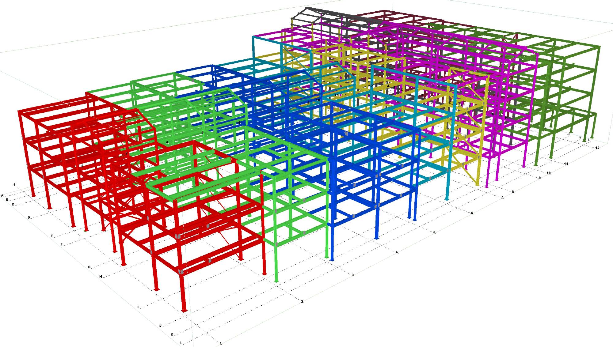
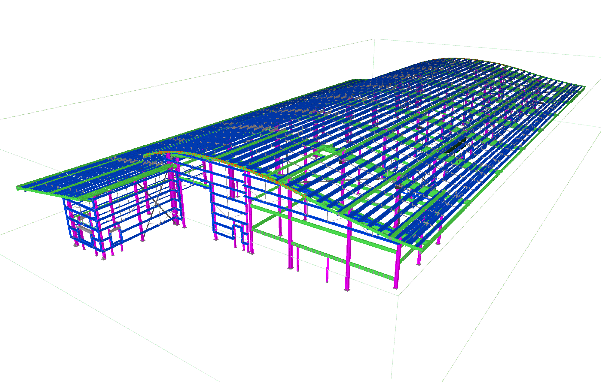
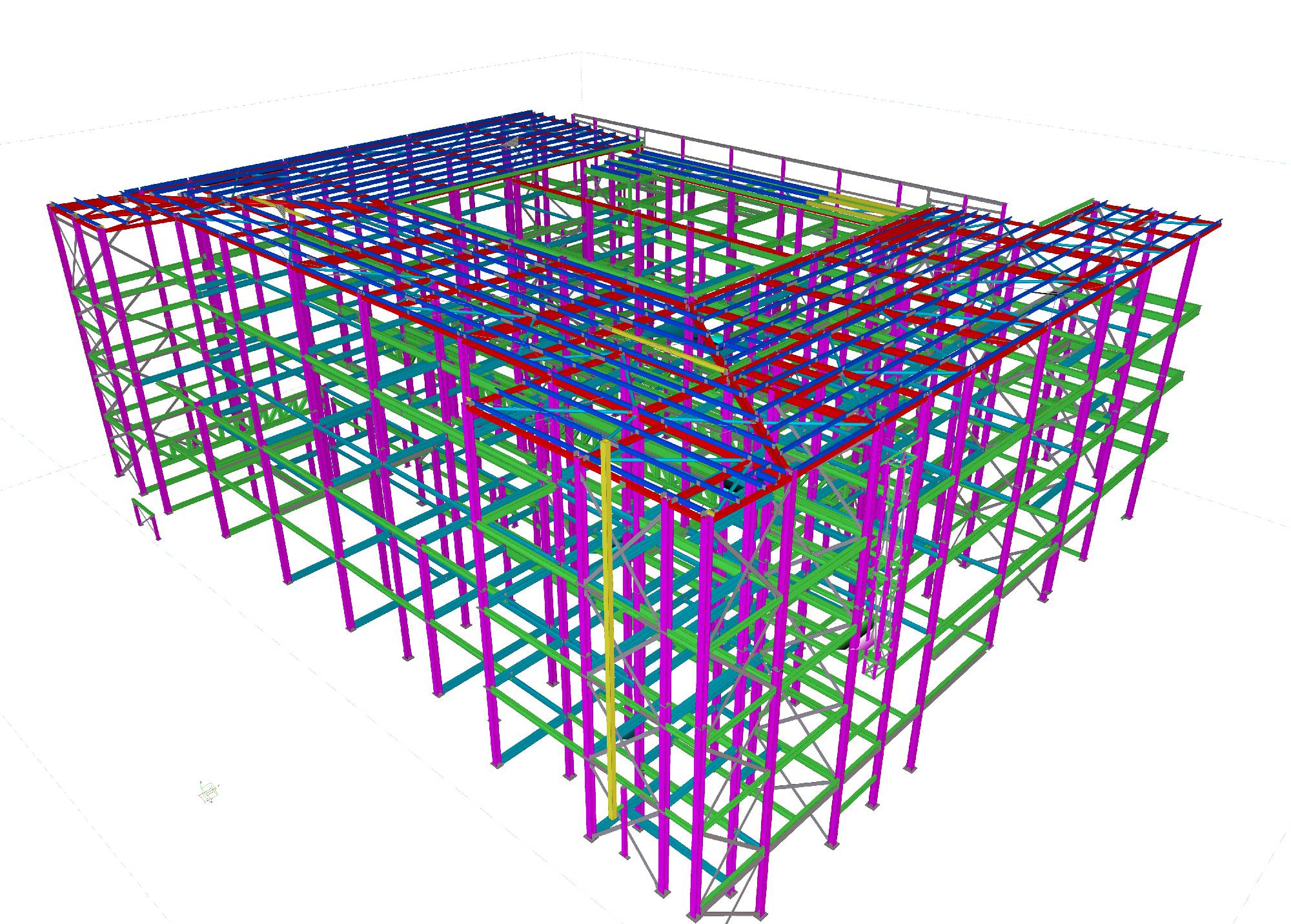
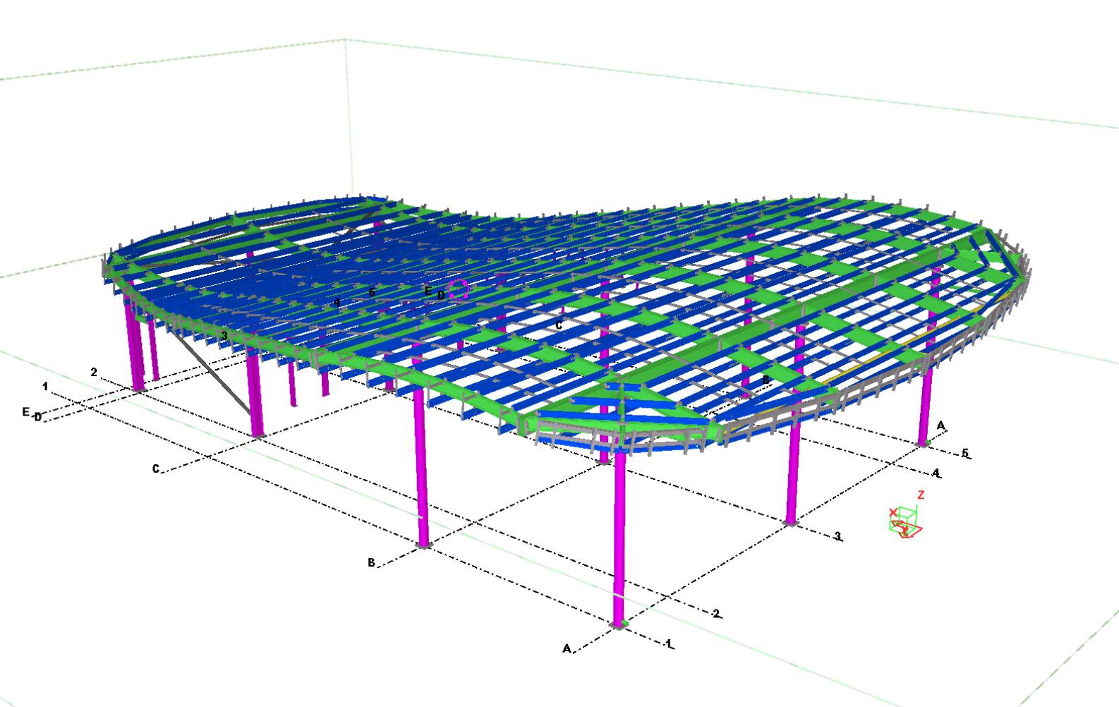
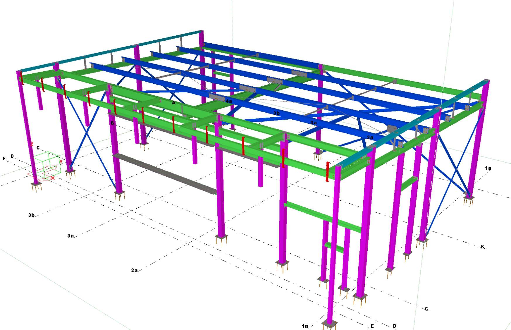
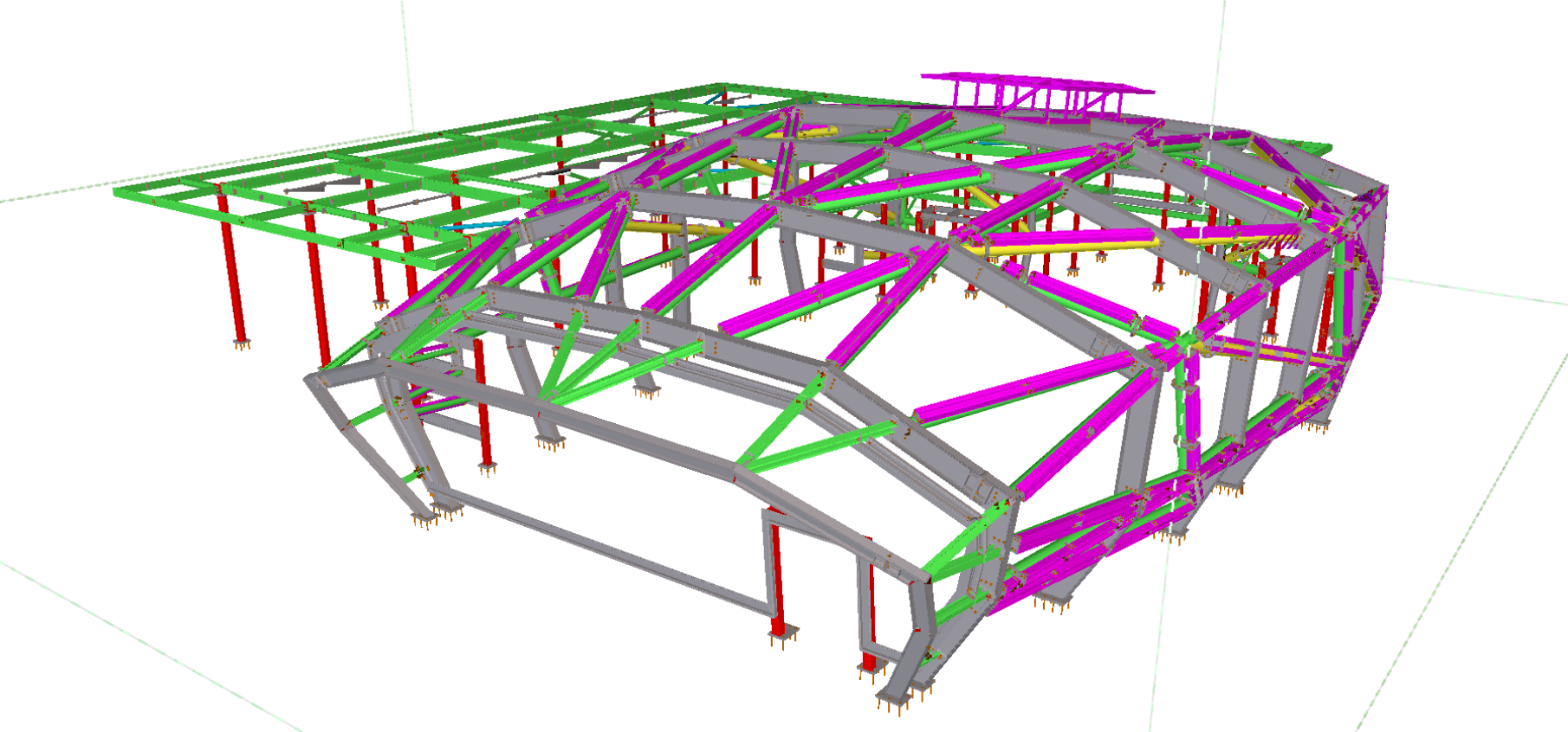
Models created with Tekla software carry the accurate, reliable and detailed information needed for successful Building Information Modelling and construction execution. Tekla works with all materials and is used on the most complex structures. The benefits of using this software for structural steel projects:-
- Precise steel detailing
- 100% accuracy for all drawings
- Library of structural steel components
- 3D environment ensuring error-free collaboration
- Always up-to-date drawings
- Simplified project revisions
- Accurate Material ordering lists & take-offs
- Erection sequencing
- Collaboration with other trades
Using our knowledge & software, we can also provide 3D virtual models via Trimble Connect.
Models can be exported as IFC files. This allows seamless coordination and integration with other design and engineering tools. Additionally, we can also import and convert IFC files created by engineers or architects, ensuring smooth collaboration. This information exchange has great benefits in coordinating building design & construction sequences, as well as highlighting any potential clashes.
BIM
We are proud to say that we currently provide BIM Level 2 conformity within our area of supply. The Government implemented a mandate in April 2016 for a minimum of Level 2. From April 2016 all originators will generate their 2D Construction drawings from a 3D model. These individual models are brought together and federated. This allows analysis and clash detection to take place ensuring that the installation is fitted once and correctly.
Four Bay Structures use Tekla Structures to build a 3D models and can use reference models, drawings or documentation provided to us through the CDE. Spatial coordination is a default output of our fully 3D workflow. As the model is developed checks are carried out at regular points, and prior to the issue of an IFC to the wider team, to ensure that any clashes within the steel frame itself are resolved. In addition the use of reference models imported into our system from our supply chain members on the project, can allow Four Bay Structures to create a coordinated model.
We work from a common data environment (CDE), usually a website-based filling system like 4Project/Viewpoint/Asite/Aconex. Where documents & design information is up-loaded & downloaded from.
On these CDE’s the main contractor usually provides a BIM Execution plan (BEP) outlining their BIM requirements from their subcontractors to follow on the contract.
We can follow document & drawing Numbering protocols, set out in the BEP. Assigning each drawing, calculation sheet etc with a unique document number & revision, as required.
If requested, we can provide an IFC model of the steel elements that we are providing. The IFC can be produced with project base point Co-ordinates assigned, that match the design teams. Allowing co-ordination between design team, clash detection & other subcontractors. IFC’s are issued with a high level of detail (LOD) & high level of information (LOI), visual representations of the members & their end connections, including plates & bolts, can be included in our IFC’s.
Drawings, IFC’s & documents are up-loaded to the CDE & are passed through their workflow with the relevant status & revisions being recorded.
We comply with the requirements for information sharing as described in PAS 1192-2:2013 and the CPIx BIM Execution Plan template.